English
| Contact Us For Quotation | Email: 464560351@qq.com | Whatsapp&Wechat:+8618620373879 |
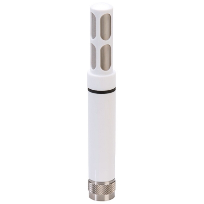
Musktool-HY130E Noise Sensor with RS485 Modbus,digital, modular, and multifunctional sound level meter
1 Overview
The HY130E noise sensor is a digital, modular, and multifunctional sound level meter. Adopting a microcontroller with DSP (Digital Signal Processing) function and digital detection technology, it has the advantages of high reliability, good stability, wide dynamic range, and no need for range conversion. It can be widely used for measuring industrial noise in various machines, vehicles, ships, electrical appliances, and can also be used for measuring environmental noise, labor protection, and industrial hygiene. |
2 Main Features and Technical Specification
1,Accuracy: ± 1.5dB, calibrated at an ambient temperature of 23 ± 5 ℃ with an input signal of 94dB (1kHz). |
2,Frequency weighting: A-weighting |
3, Time Weighting: F(125ms) |
4, Frequency Range: 20 Hz ~ 12.5 kHz |
5,Working Environment Conditions: Air temperature: -10 ℃~+50 ℃ ,Relative humidity: 20%~90%, Static pressure: 65 kPa~108 kPa |
6,Measurement range at 1 kHz frequency: 30 dB(A) ~ 130 dB(A) |
7, Resolution: 0.1 dB |
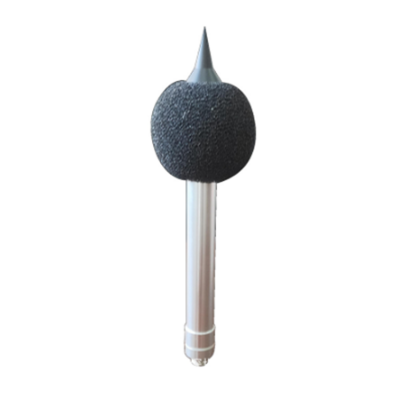
8,Microphone: 0.5 inch capacitive microphone |
9,The impact of using a hood: Within an important frequency range, not exceeding 0.5 dB |
10,Power Supply: DC 12V |
11, Output: RS485/MODBUS |
12,Power consumption: Approximately 230 mW |
13,Product material: The metal rod is made of aluminum alloy material |
14, Weight: About 160g, (Including protective cover and windproof cover, excluding cable line, cable line default is 2m) |
3, External dimensions

3 Usage and operation
3.1 wiring method
Different models of instruments correspond to different wiring methods. If wiring errors occur, they may cause permanent damage to the instruments.
Table1 Wiring Method
PIN | Output Signal | ||
Voltage | RS485 | Color | |
PIN 1 | Power(+) | Voltage(+) | white |
PIN 2 | Power(-) | Power(-) | Yellow |
PIN 4 | Signal | A485+ | Black |
PIN 5 | Signal | B485- | Red |
Attention: For the convenience of connection, sockets are introduced between the leads. Please pay attention to the connection between the sockets. The sockets have card slots. Before powering on, check that the sockets are connected properly, otherwise it may burn out the instrument
3.2 0-5V DC Output
For instruments with 0-5V DC output, the calculation formula is as follows:
L=20×U+30.0 ……………………(1)
Among:
U——Output Voltage,V;
L——Tested sound level,dB(A)。
For example:if U=3.2V,then L=20×3.2+30.0=94.0 dB(A)。
3.3 ModBus Protocol
3.3.1 Communication parameters
8 data bits, 1 stop bit, no parity check, baud rate 9600Bd (customizable according to user needs). CRC is a 2-byte checksum, with low bytes before and high bytes after. If connecting to a computer and using serial debugging software to send and receive data, please set the software to HEX (hexadecimal) for sending and receiving. |
3.3.2 COMMUNICATION FORMAT
The default device address for sensors at the factory is 1, and the adjustable address range is 1-255. If multiple sensors need to be connected to the same communication network, please make sure to first set new device addresses independently for each sensor (see 【 1 】 and 【 2 】), otherwise it will cause network communication failure.
【1】Write device address(For example to write address 01)
Send | 00 | 10 | 01 | 00 | 01 |
Explain | broadcast address | Command | New Address | CRC | |
Return | 00 | 10 | 00 | 7C | |
Explain | broadcast address | Command | CRC | ||
【2】Read device address(For example:Read device of address1)
Send | 00 | 20 | 00 | 68 | |
Explain | broadcast address | Command | CRC | ||
Return | 00 | 20 | 01 | A9 | C0 |
Explain | broadcast address | Command | Device address | CRC | |
【3】Read register data(For example, reading data from a device with address 3)
Send | 03 | 03 | 00 | 00 | 00 | 01 | 85 | E8 |
Explain | Device address | Command | start address | Read points | CRC | |||
Return | 03 | 03 | 02 | 02 | FD | 01 | 65 | |
Explain | Device address | Command | Data Bytes | Device data | CRC | |||
The data returned by the sensor is 0x02FD, converted to decimal 765, indicating a noise value of 76.5dB with 1 decimal place.
【4】Read calibration sound level (e.g. read calibration sound level for device with address 3)
Send | 03 | 04 | 00 | 09 | 00 | 01 | E0 | 2A |
Explain | Device address | Command | Start Address | Read points | CRC | |||
Return | 03 | 04 | 02 | 03 | AC | C0 | 7D | |
Explain | Device address | Command | Start Address | Calibration sound level | CRC | |||
The data returned by the sensor is 0x03AC, converted to decimal as 940, indicating a calibrated sound level of 94.0dB with 1 decimal place.
【5】Modify the calibration sound level (e.g. modify the calibration sound level of a device with address 3)
Send | 03 | 06 | 00 | 09 | 03 | 48 | 58 | EC |
Explain | Device Address | Command | Start address | Calibration sound level | CRC | |||
Return | If the modification is successful, return the same as sending. | |||||||
The calibration sound level to be modified is 0x0348, converted to decimal as 840, indicating a calibration sound level of 84.0dB with 1 decimal place.
【6】Calibrate sensors (e.g. for devices with calibration address 3)
Send | 03 | 06 | 00 | 01 | 00 | 01 | 18 | 28 |
Explain | Device Address | Command | Start Address | Calibrate | CRC | |||
Return | If the modification is successful, return the same as sending. | |||||||
First, unscrew the wind hood, then open the sound calibrator to make a 94.0dB sound, insert the sensor into the coupling chamber of the sound calibrator, and send the above calibration command. Wait for at least 6 seconds.
4 Precautions
1) Please check if the packaging is intact and verify if the product model matches the selection; 2) Do not connect live wires. Only after wiring is completed and confirmed to be correct can power be applied; 3) The length of the sensor wire can affect the output signal of the product. When using it, do not arbitrarily modify the components or wires that have been welded before the product leaves the factory. If there is a need for modification, please contact the manufacturer; 4) Sensors belong to precision instruments. Users should not disassemble them themselves when using them. Use sharp objects or corrosive liquids to contact the surface of the sensor to avoid damaging the product; |
5 Fault Analysis and Troubleshooting
Unable to obtain data or incorrect data during RS485 or analog output. 1) Please check if the wiring is correct and secure, and if the length exceeds the specified length; 2) Please check if the external power supply voltage is consistent with the purchased model; 3) If connected to a computer, please check if the computer's serial port is occupied and if the serial port settings are correct; 4) If connected to a computer, please check if the corresponding RS232 or RS485 converter is working properly; 5) If connected to PLC, configuration or programmable data acquisition devices, please check if these devices are working properly. If it is not for the above reasons, please contact the manufacturer. |